Description
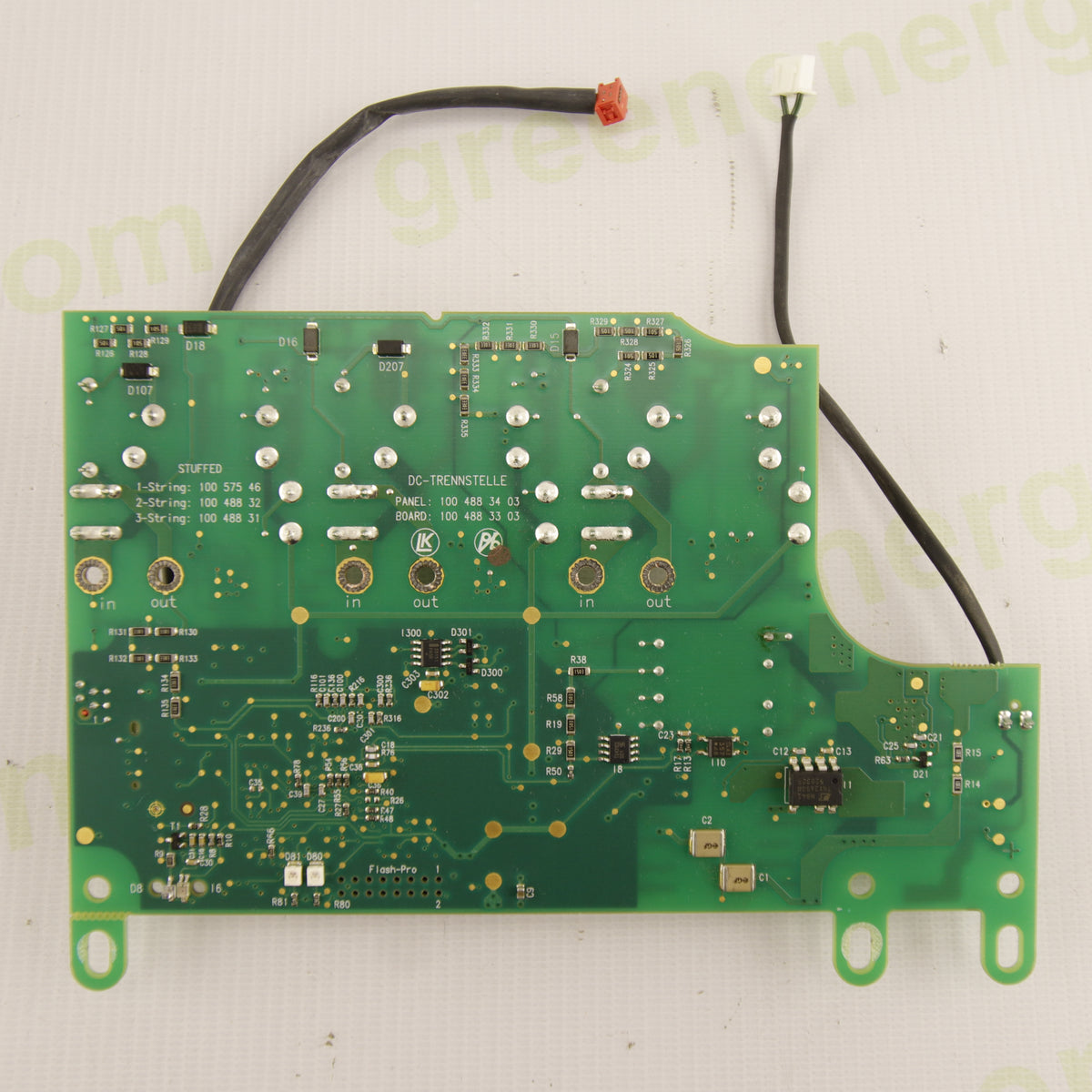
Used product. Original KOSTAL PIKO DC-TRENNSTELLE electronic board, used in the DC input system of first-generation KOSTAL PIKO photovoltaic inverters. The DC-Trennstelle is the electronic section dedicated to the connection, disconnection, and management of photovoltaic strings in direct current, with power supply, control, and power relay drive circuits.
The photographed board features a 3-String configuration. It includes three power relays, power supply circuitry, switching components, transformers/inductors, driver circuits, and interface connectors. KOSTAL used the electronic DC-Trennstelle in PIKO inverters to manage photovoltaic generator disconnection on the DC side.
⚙️ Technical Specifications
-
Manufacturer: KOSTAL
-
Function: DC-TRENNSTELLE / Electronic DC Disconnect
-
Visible configuration: 3-String
-
Power relays: 3
-
Visible connectors: X2, X3, X4, X5, X6, X7
-
Power supply circuit: integrated on the PCB
-
Control circuits: integrated for relay and DC sequence management
-
Construction: industrial PCB with discrete components, relays, switching circuits, transformers/inductors, and connections for the inverter DC system.
⚡ Function in the Photovoltaic System
The DC-Trennstelle is located in the inverter input section and electronically manages the connection and disconnection of the PV strings to the power electronics.
During PIKO startup, the board participates in the power supply and control sequence required to allow correct transfer of DC voltage to the subsequent inverter sections. Correct operation of the relays and the board's auxiliary power supply is therefore essential for completing the startup procedure.
🔧 Faults, Errors & Symptoms
A fault in the DC-Trennstelle can cause situations where the inverter receives voltage from the panels but fails to complete startup.
Symptoms may include:
- inverter remaining “Aus / Off” despite the presence of DC voltage;
- failure to detect or transfer DC voltage to the subsequent stage;
-
DC relays failing to switch;
- relays producing repeated clicks during the startup attempt;
- display values unavailable or shown as “XXX” during the startup procedure;
- inverter failing to correctly detect DC and/or AC during the initial phase;
- status LEDs showing an abnormal sequence or absence of normal initialization;
- failure to restart after shutdown;
-
intermittent operation, with the fault potentially varying depending on temperature or after a power supply reset;
- inverter apparently switched off despite significant PV voltage being present at the input.
In particular, the “XXX” error/symptom during startup, when the inverter fails to correctly detect DC/AC parameters, may be associated with a DC-Trennstelle problem, but it is not an exclusive diagnostic code for this board.
🛠️ Possible Repair Work
The board can undergo component-level electronic repair. Among the faults reported on DC-Trennstelle boards of this generation are problems in the power supply section, including loss of capacitance of capacitor C4 and faults/desoldering of diode D10.
During a professional inspection, the following may be checked:
-
electrolytic capacitors, particularly in the power supply section;
- diodes and switching circuit;
- driver transistors;
- auxiliary power supplies of the board;
- voltages used to control the relays;
-
coils and contacts of the three DC relays;
- transformers and magnetic components;
- solder joints, tracks, and connections;
- connectors and wiring;
- control and feedback circuits.
Repair of the DC-Trennstelle can therefore resolve startup failure, relays not switching, intermittent startup, and conditions in which the PIKO remains switched off or displays “XXX” despite photovoltaic voltage being present.
Important: not all PIKO startup problems are necessarily caused by the DC-Trennstelle. Similar symptoms can also be caused by the power board, DC-DC converter, wiring, power supplies, or other sections of the inverter. Diagnosis must therefore be carried out on the complete inverter.
🌐 Compatibility & Applications
The DC-Trennstelle of this generation is associated with first-generation KOSTAL PIKO DCS inverters. The replacement-parts market lists it for various versions of the PIKO family, including PIKO 3.0, 3.6, 4.2, 5.5, 7.0, 8.3, and 10.1.
Compatibility must nevertheless be verified by comparing the PANEL, BOARD, PCB revision, and inverter configuration, as different versions of the DC-Trennstelle may exist.
🏭 Construction & Product Condition
The photographed board is used and shows normal signs of use, handling, and previous installation. Three power relays, electronic components, transformers/inductors, power supply circuits, and original connectors are visible.
No major structural damage to the PCB is evident from the photographs. Operation is not declared as tested, unless specifically indicated in the sale.
🛡️ Safety
The DC-Trennstelle operates on the photovoltaic DC circuit, where high and dangerous voltages may be present even with the AC grid disconnected.
Installation, replacement, and especially repair must be carried out exclusively by qualified personnel, following the safety procedures required for PV inverters. After repairing the board, insulation, tightening, connections, compatibility, and inverter operation under high voltage must be correctly verified.
📦 Package Contents
1 × KOSTAL PIKO DC-TRENNSTELLE electronic board
🚀 Final Description
The KOSTAL PIKO DC-Trennstelle is an original electronic board designed for the management and disconnection of DC strings in first-generation KOSTAL PIKO photovoltaic inverters. The presence of three power relays and the associated power supply and control circuitry makes it a fundamental component in the startup sequence and photovoltaic input management.
It is a particularly interesting replacement part for PIKO inverters presenting startup failure, an apparently switched-off inverter with DC voltage present, relays failing to switch, intermittent startup, or “XXX” displayed during the initialization phase. Electronic servicing may particularly involve the power supply section, including C4, D10, switching circuit, relay drive, and related components.