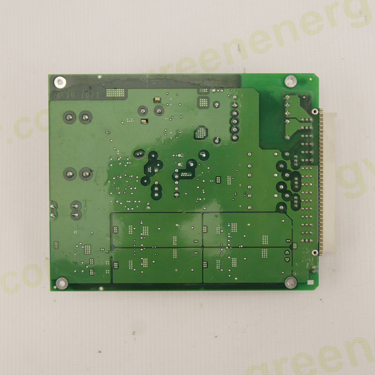
Aurora Power-One 3F50-99-1 | PVI-Central 50/55 kW PCB
Impossibile caricare la disponibilitΓ di ritiro
Discount
|
Spend β¬500+ |
3% OFF |
|---|---|
|
Spend β¬3 000+ |
5% OFF |
|
Spend β¬8 000+ |
10% OFF |
|
Spend β¬12 000+ |
Custom Quote |
Acquista in sicurezza
Rendi sicura la tua esperienza di acquisto con diversi metodi di pagamento sicuri e affidabili.
Semplice e senza stress β gestiamo i problemi senza burocrazia.
Dallβinstallazione alle domande β siamo al tuo fianco anche dopo la vendita.
Descrizione
π Description
Used product. Original POWER-ONE 3F50-99-1 β Pb-free electronic board, belonging to the modular architecture of Aurora Power-One centralized photovoltaic inverters, subsequently marketed under the ABB and FIMER brands.
This inverter family was designed for commercial, industrial and large-scale solar power plants, with a modular structure based on removable power drawers/modules. FIMER officially describes the PVI-55.0/330.0 series as a family of modular centralized inverters based on 55 kW removable modules, configurable in different power ratings.
The 3F50-99-1 board is associated with the internal electronics of the power modules of the PVI-Central platform, with particular reference to the 3I19 module. FIMER documentation officially identifies the PVI Central β 50/55 kW Module, PN 3I19 and distinguishes the module configurations according to the rack.
βοΈ Main Specifications
- Brand: Power-One / Aurora
- PCB Code: 3F50-99-1
- Version: Pb-free
- Electronic board inside the power module/drawer
- Used in the architecture of three-phase centralized inverters
- Transformers, inductors and conversion circuits
- Filtering and power supply circuits
- Electrolytic capacitors
- Relays and interface circuits
- Multipole connector for connection with the rest of the module
The PVI-Central 50 kW platform officially provides a 50 kW power module; in the later configurations of the PVI-55.0 family, FIMER instead describes 55 kW removable modules.
π§ Main Functions
The 3F50-99-1 performs functions within the module electronics related to:
- auxiliary circuit power supply;
- distribution of internal power supplies;
- voltage conversion and filtering;
- interfacing between the different electronic sections;
- management of auxiliary circuits through relays and dedicated components;
- support for the correct operation of the module control electronics.
π Purpose and Operation
The board operates inside the removable power drawer/module of the centralized inverter.
The fundamental concept of this platform is modularity: instead of using a single high-power electronic stage, the system uses conversion modules/drawers that can be installed in different configurations.
This structure allows maintenance work to be carried out on individual modules, reducing the impact of a fault on the overall plant availability.
π§© Compatibility
Main references:
- Power-One Aurora PVI-Central
- PVI-Central 50/55 kW
- PVI-Central Module PN 3I19
-
PVI-55.0 / PVI-Central family
FIMER officially identifies PN 3I19 as a 50/55 kW PVI Central module. The same documentation distinguishes other module configurations; therefore, this PCB must not be considered universally interchangeable between all models.
β οΈ Before purchasing, always verify: - 3F50-99-1 code;
- PCB revision;
- connector type and arrangement;
- drawer configuration;
- inverter model and version.
β οΈ Typical Faults and Symptoms
A board malfunction may contribute to:
- module startup failure;
- absence or instability of auxiliary power supplies;
- module reset;
- intermittent operation;
- loss of communication with the control electronics;
- failure to recognize the module;
- power drawer shutdown;
- abnormalities during initialization;
- persistent faults.
These symptoms do not automatically prove that the 3F50-99-1 is faulty. Before replacement, the power supplies, wiring, connectors, control boards, drivers and power section must also be checked.
π¨ Possible Associated Errors
Official FIMER documentation for PVI-Central systems reports several module diagnostic codes, including:
- E004 β Bulk OV: capacitor voltage above the maximum threshold.
- E005 β Communication: communication error with the DSP.
- E006 β OC: output current above the maximum threshold.
- E007 β OCH: IGBT current above the threshold or IGBT saturation.
- E014 β Over Temp: overheating.
- E015 β Delta Bulk: DC capacitor voltage difference above the threshold.
- W010 β Fan Fail: left fan blocked.
- E038 β FAN Stuck: center/right fan blocked.
- E041 β Relay AC: internal AC contactor did not switch.
- E042 β Bulk UV: capacitor voltage below the minimum threshold.
-
E043 β Auto Exclusion: automatic module exclusion after repeated faults.
These are system/module errors and not codes specific to the 3F50-99-1 board. Their presence must be used as an indication for diagnosis of the complete module.
β οΈ E031 β Wrong V Measure
Particular attention should be paid to code E031.
It is not correct to generically describe E031 as βoutput relays faultyβ for this platform. FIMER/Power-One documentation associates E031 β Wrong V Measure with an abnormality in voltage measurement. Diagnosis should therefore consider the measurement chain and associated electronics, not only the relays.
β οΈ E032 β Wrong I Measure
E032 β Wrong I Measure indicates an abnormality in the electrical measurement associated with the system's current/voltage circuit. Again, this code does not directly identify the 3F50-99-1 as the responsible component, and the measurement chain must be diagnosed.
β οΈ E034 β Interlock Fail
E034 β Interlock Fail / IGBT Not Ready indicates a condition in which the IGBT electronics are not ready. This is an internal fault requiring inspection of the control chain and power section; it must not automatically be attributed to the 3F50-99-1.
π Diagnosis
To check the board, it is advisable to inspect:
- auxiliary power supply voltages;
- transformers;
- switching circuits;
- inductors;
- relays;
- capacitors;
- power components;
- regulation circuits;
- solder joints and PCB traces;
- connectors;
- possible short circuits;
- overheated or damaged components.
In the presence of a module fault, it is important to distinguish a board problem from a failure of the IGBTs, Bulk capacitors, drivers, ventilation system, sensors or measurement circuit.
π οΈ Common Services in Case of Failure
- Electronic PCB diagnostics.
- Power supply checks.
- Faulty component identification.
- Transformer and switching circuit inspection.
- Capacitor inspection.
- Relay inspection.
- Inductor inspection.
- PCB trace and solder inspection.
- Replacement of damaged electronic components.
- Functional testing after repair.
π οΈ Applications
Replacement part for maintenance and repair of Power-One Aurora / ABB / FIMER three-phase centralized photovoltaic inverters, intended for commercial, industrial and large-scale ground-mounted photovoltaic plants.
In particular, the board is associated with the PVI-Central 50/55 kW architecture and 3I19 module, subject to verification of the code and hardware configuration.
π‘ Advantages
- Original Power-One electronic board.
- Replacement part intended for high-power centralized inverters.
- Suitable for professional maintenance and repair activities.
- Allows work on the individual electronic circuit without necessarily replacing the entire module.
- Particularly useful for restoring and maintaining discontinued Aurora Central inverters.
π‘οΈ Product Condition
Used product, with cosmetic condition as shown in the photographs.
The board is supplied in the condition shown. Before installation, verify the PCB code, revision, connectors and module configuration.
π¦ Package Contents
- 1 Γ Power-One 3F50-99-1 Pb-free electronic board, as shown in the photographs.
π’ Summary
The POWER-ONE 3F50-99-1 is an electronic board belonging to the modular architecture of Aurora Power-One centralized inverters, subsequently marketed under the ABB/FIMER brands.
It is intended for the internal electronics of removable power modules/drawers, with reference to the PVI-Central 50/55 kW β PN 3I19. These are three-phase industrial machines designed for large-scale photovoltaic plants.
The board performs auxiliary power supply, conversion, filtering and electronic interfacing functions within the module. A malfunction may contribute to startup, power supply, communication or drawer operation problems, but the error codes must be interpreted as diagnostic indications for the complete system and not as automatic proof of PCB failure.
β οΈ Safety Note: Work on centralized inverters and power modules must be carried out exclusively by qualified personnel, following the isolation, securing and voltage-absence verification procedures specified by the manufacturer.
Got a question?
Don't be a stranger.
Fare acquisti in sicurezza
Nel nostro negozio Shopify, diamo prioritΓ alla tua sicurezza e protezione. Ecco come garantiamo un'esperienza di acquisto sicura:
1. Transazioni sicure: utilizziamo una crittografia avanzata per proteggere i tuoi dati personali e di pagamento, garantendone la trasmissione e la salvaguardia in tutta sicurezza.
2. Gateway di pagamento affidabili: il nostro negozio si integra con gateway di pagamento affidabili, garantendo che le tue transazioni vengano elaborate in modo sicuro ed efficiente.
3. Privacy dei dati: la tua privacy Γ¨ la nostra massima prioritΓ . Seguiamo rigide politiche di protezione dei dati per mantenere le tue informazioni personali riservate e sicure.
4. Piattaforma sicura: Shopify offre solide funzionalitΓ di sicurezza e monitoraggio continuo contro le vulnerabilitΓ , garantendo un ambiente di acquisto sicuro.
5. Commercianti verificati: siamo un commerciante verificato su Shopify, impegnato a fornire prodotti autentici e di alta qualitΓ .
6. Politiche trasparenti: le nostre chiare politiche di reso, rimborso e spedizione garantiscono tranquillitΓ , sapendo che garantiamo i nostri prodotti.
7. Assistenza clienti: il nostro team dedicato all'assistenza clienti Γ¨ pronto ad aiutarti con qualsiasi dubbio o domanda tu possa avere.
Acquista in tutta sicurezza nel nostro negozio Shopify, dove la tua sicurezza e soddisfazione sono le nostre massime prioritΓ .
π Termini e condizioni di garanzia
Effettuando un ordine, lβacquirente riconosce e accetta la seguente politica di garanzia:
β Garanzia di 1 anno per inverter
-
Tutte le unitΓ di inverter solari sono coperte da una garanzia di 1 anno dalla data di acquisto.
-
Ogni unitΓ viene completamente ispezionata e testata prima della spedizione per garantirne il corretto funzionamento.
π§ Cosa copre la garanzia
-
La garanzia copre difetti e malfunzionamenti che si verificano durante il normale funzionamento.
-
Sono inclusi lβinverter nel suo complesso, i componenti interni e le schede elettroniche.
-
In caso di problemi entro il periodo di garanzia, provvederemo alla riparazione o sostituzione del componente o prodotto difettoso, in conformitΓ con la nostra politica di garanzia.
π Garanzia per componenti separati
-
Per schede elettroniche interne, componenti e kit di riparazione ordinati separatamente, si applica una garanzia di 6 mesi dalla data di acquisto.
-
Entro questo periodo, qualsiasi guasto funzionale comporterΓ la sostituzione gratuita secondo i nostri termini di garanzia.
β οΈ Cosa non copre la garanzia
La garanzia non si applica nei seguenti casi:
-
Installazione impropria da parte del cliente o di terzi
-
Sovratensione di rete
-
Fulmini o altri danni ambientali/esterni
β Si raccomanda di garantire lβinstallazione corretta da parte di un tecnico qualificato. Collegamenti o manipolazioni improprie annullano la garanzia.
β¬650,00 EUR